

Design Project 3 - Urban Solid Waste Management
- Nov 30, 2016
- 19 min read
1.0 Introduction

Figure 1: (Hypothetical) Flooding of Wyandotte, MI (www.wunderground.com)
1.1 Background History of Ioskeha
In the spring of 2014, the lives of the 25,000+ citizens of Wyandotte, Michigan changed forever. A historic flooding of the Detroit River led to major devastation in the city. Most of the infrastructure, including the roads, public buildings, and residential households, were wiped out. Instead of moving away from their beloved hometown, the citizens of Wyandotte came together to rebuild and recreate. They started by changing the name of the city to Ioskeha, named after the sun-god of the Iroquois, who originally had a small village on the site. With the sun-god on their side, the citizens began promoting a green culture throughout the city through teaching and volunteering, as well as implementing green engineering in the rebuilding of the infrastructure of the city. While the city is still under construction, the changes that have already been have been favorable amongst the citizens and have set the example for other, potentially green communities to follow.
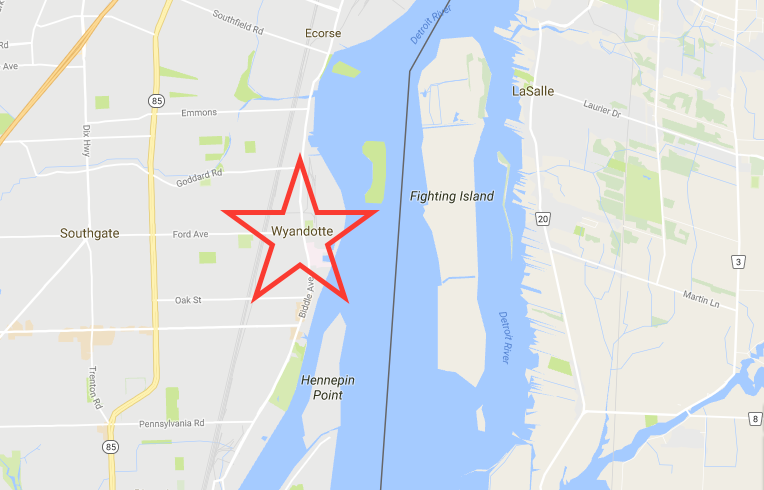
Figure 2: Location of Wyandotte, MI, now Ioskeha. (Google Maps)
1.2 Becoming a Green Community
After hearing about the flooding in Ioskeha, a former resident who moved to Georgia to attend the University of Georgia’s environmental engineering program and went on to start her own environmental engineering consulting firm, moved back home to help the citizens of her hometown start over. With help from the firm, the citizens were able to implement changes to make their city more environmentally friendly. They started with the energy source. Wind turbines were built just outside the city to provide a renewable source of energy to the city. In addition, a biomass plant was also built outside the city to provide an additional source of energy. The biomass plant also provided jobs to the city after the flood. The plant runs off of burning wood. A natural gas electric generating plant located in the next town is used as a backup source of energy when the wind turbines and biomass plant are not enough to provide the residents with adequate energy. However, the natural gas backup source to the city has rarely been in service since the flood because energy efficient buildings and homes were designed for the city. Most homes and public buildings house EnergyStar appliances, which are much more efficient than other appliances. In addition, LED lighting was installed for all public street lights, and citizens were offered discounted LED lighting for their homes if they chose to install them. Biking and public transportation are strongly encouraged throughout the city with biking lanes designed for every major road in the city and electric public buses making stops inside and outside the city. An electric car sharing program was implemented to encourage less driving as well, and electric car charges were installed at all public buildings to encourage residents to purchase electric cars. A green culture was started in the city of Ioskeha as well. In order to promote a "green culture", Ioskeha has encouraged citizen and community involvement. This includes a community garden, where local high school students can volunteer as a class elective, weekly classes about new green engineering and energy technologies, and monthly meetings to discuss changes that can be made to make the community even better.
1.3 Firm Introduction and Goal
The firm hired to help rebuild the city, founded by a former Wyandotte resident and UGA alum, is LSE Engineers, Inc. This firm focuses on green engineering and producing sustainable design projects. LSE Engineers, Inc. focuses on affordable, sustainable, context sensitive designs that are approved and supported by all citizens wherever they are serving. LSE Engineers incorporates a number of principles to help promote green engineering and sustainable development. LSE Engineers work to use nonhazardous materials, as well as materials that can be recycled or reused for another purpose after they are used in the design. These materials must be durable, able to withstand many years to avoid rebuilding/replacing and wasting material. In addition, LSE Engineers makes sure that the materials and components used in the design are easily dismantled and replaced if necessary over the lifetime of the facility. LSE Engineers focuses on producing as little wastes as possible, both during the building process and after the facility/building has been completed. For this urban solid waste management design, LSE Engineers will work to make planning, building, and operation of the system as efficient as possible. The design will include a landfill that will collect a majority of the city’s waste. The landfill will be designed to promote safe and efficient storage of waste. The landfill gas produced at the facility will be captured and used to power a new community college that will be opening in the city in the upcoming year. In addition, the leachate from the landfill will be captured, treated, and then used to irrigated the area surrounding the landfill. The garbage and recycling pick-up trucks will be electric vehicles that are charged each night at the facility thanks to a government grant. In addition, LSE Engineers, Inc. hopes to promote recycling in the city of Ioskeha. While Michigan’s recycling rate is low at 15%, the town of Ioskeha is looking to improve that rate by implementing single stream curbside recycling at all residential homes, as well as multifamily recycling options. Pay-as-you-throw policies will be implemented as well to encourage recycling. Compost pickup will be optional for customers for a small fee, but compost drop-off is available at the materials recovery facility located in the town. If composting becomes a large part of the community, pickup schedules could be adjusted to include compost pickup. Over the course of 25 years, Ioskeha hopes to improve the recycling rate in the city to 40%, but the landfill system will be designed to contain the amount of waste generated if the recycling rate stayed at 15% for a safety factor. The materials recovery facility will be designed to process the higher recycling rate if the goal is achieved. This solid waste management system will be designed to meet all national, state, and local standards, including the standards outlined in Resource Conservation and Recovery Act and the Pollution Prevention Act.
1.4 Public Meeting Notice
The design for this urban solid waste management system is being proposed on November 30th at 12:30pm in a town hall type meeting. As citizens of Ioskeha, you are encouraged to attend if possible, and all questions and
concerns will be addressed.
1.5 Report Objectives
In addition to the proposal of the project at the meeting on Wednesday, November 30th, this report is designed to outline the new urban solid waste management system. This facility is being designed to process and store the solid waste from 25,000+ people, which takes into account the possibility of future growth. This report will discuss the background information of the waste generated in Ioskeha, the proposed locations of both facilities, and the actual design of both of the facilities. Once again, this is the proposed solution for the urban solid waste management system. All concerns for this design will be addressed at the town hall meeting.
2.0 Background
2.1 Waste Generated
The purpose of this urban solid waste management system is safely collect, process, and dispose of all solid waste generated in the town of Ioskeha. Solid waste is made up of the everyday items that are discarded by the public. This solid waste management system is designed to encourage reduction and recycling, protect public health, protect the environment, address all social concerns that the citizens may have, and minimize all costs, including economic, social, and environmental costs. The system will manage residential, commercial, construction and demolition, institutional, and municipal services waste. The system will include a landfill and a materials recovery facility where waste will be recovered and sold in bulk to companies that will recycle the material. In addition, there will be a facility on site at the landfill that will take in hard to recycle materials like batteries, computers, light bulbs, etc. The waste management system will follow all standards set by the national government through the Resource Conservation and Recovery Act, which sets a framework for the management of non-hazardous solid waste, as well as the generation, transportation, treatment, storage, and disposal of hazardous waste. It will also follow the standards set by the Pollution Prevention Act, which works to reduce pollution through operation and production changes, as well as the use of raw materials. In addition, the system will adhere to the local and state standards that are already in place.
In Michigan, data collection about waste generation is nearly non-existent. For this reason, Michigan uses the national average per capita waste generation rate to determine the amount of waste generated per year in the state. Therefore, LSE Engineers, Inc. used the national per capita waste generation rate to determine the size of the landfill needed to contain the waste generated by the city. This rate was determined to be 4.4 pounds per person per day. Using the current population of Ioskeha set at 25,592 people, the total waste generated per day was determined to be 112,604.8 pounds. The waste generated per year was found to be 20,550.376 tons before recycling. This waste generation rate is used for each year for this waste management design since the population of Ioskeha is actually decreasing. Therefore, this rate will actually be an overestimate of the amount of waste generated, but it will be used as a factor of safety in the design of the system. Using the current recycling rate for Michigan, set at 15%, the total amount of waste recycled was calculated to be 3,082.56 tons per year, which will also stay constant for this design. However, the materials recovery facility will be designed to eventually handle approximately a 40% recycling rate. This would equate to approximately 8,220.15 tons per year of waste going through the materials recovery facility. If this is recycling goal is met, the life of the landfill will be further increased. Therefore, LSE Engineers, Inc. is proposing to just build one phase of the landfill at a time, as needed. The current design, further explained in later sections, currently has a lifetime of 50 years, which is a conservative estimate. Therefore, part of the landfill may not need to be constructed for many years in the future. Based on the current population and the waste generation per capita rate, the amount of waste going to the landfill each year is 17,467.816 tons. If the recycling rate does reach 40% in the future, the amount of waste going to the landfill each year will be reduced to 12,330 tons per year. While this design does not take this change into consideration, the reduction in waste going to the landfill will only increase the life of the landfill.
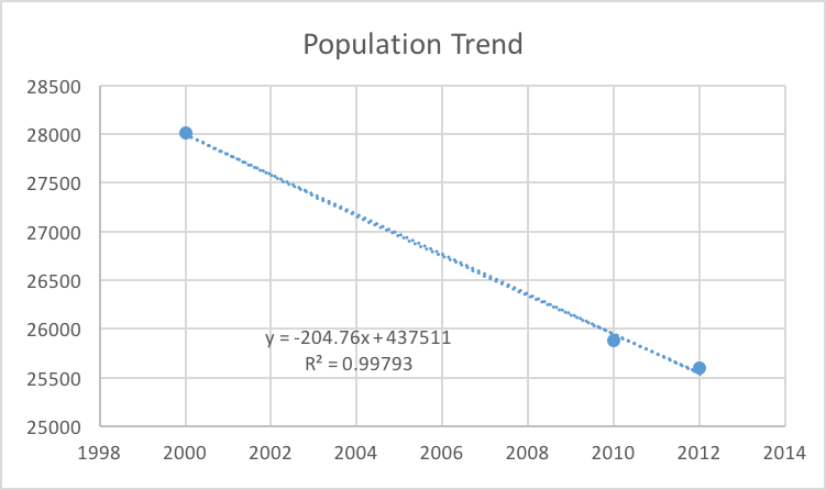
Figure 3: Predicted population trend; since it is decreasing, LSE decided to use the current population as the max population. (Excel)
2.2 Characterization of Waste
Due to lacking state data about the characterization of waste generated for Michigan, LSE Engineers, Inc. used national data to characterize the waste generated for the town of Ioskeha. Included in the waste generated by the town is 5000 tons of “other” waste. This waste is imported from Canada and processed by the system in Ioskeha. This is due to a lack of facilities in Canada, and presents an economic opportunity for the facilities located in Ioskeha. This “other” waste is made up of industrial waste from some of the cities located across the river from Wyandotte. This waste is imported via ferries across the river. The pie charts below break down the waste for a visual representation.

Figure 4: Pie graph of the breakdown of waste generated in Ioskeha (20,550.376 tons/year)
Out of the total waste generated in Ioskeha and imported from Canada, approximately 15% of that waste is recycled each year. This adds up to 3082.56 tons per year of recycled material being processed in the Materials Recovery Facility. The breakdown of that recycled material by type is demonstrated in the pie chart below.

Figure 5: Pie chart of the breakdown of recycled material generated in Ioskeha (out of 3082.56 tons/year)
The materials recovery facility will be designed to handle this breakdown of recycled material, as well as the possible increase in the amount of recycled material to 8220.15 tons per year. This amount of recycled material includes composted material, which makes up 29% of all the material that is recycled (yard trimmings + food). Composted material can be processed at the materials recovery facility.
2.3 Location of Each Facility
Both the landfill and the materials recovery facility will be located out of the town of Ioskeha and away from neighborhoods in a mainly rural, industrial area. This is to avoid any noise, smell, or site disturbances for the general public. However, the sites will be located near roads to allow for easy access to the public if there is the need to drop of composted materials, hard to recycle materials, or recycled material/waste that was missed on pick-up day. The location of each facility is marked below.

Figure 6: Image of proposed locations for the Materials Recovery Facility and Landfill. (Google Maps)
3.0 Materials Recovery Facility
3.1 Overall Design Goal and Purpose
The overall purpose of this materials recovery facility is to collect all recyclable materials from commercial, residential, and industrial customers, and then process it at the facility. The processing step involves separating the materials into their different components. This facility is designed to process up to a 40% recycling rate by the citizens of Ioskeha for future improvement. Below is a chart containing the types of materials that can be recycled by the plant versus what cannot be recycled at the plant. Items that cannot be recycled, as well as impure items, will be taken from the recovery facility and transported to the landfill. There is also a hard to recycle facility located at the landfill. The chart below also dictates these hard to recycle items that can be taken to this facility by the consumers if they choose to recycle them.

Figure 7: Chart describing what can and cannot be recycled at the materials recovery facility and the hard to recycle facility
3.2 Types of Recycling
This waste management system is being designed to handle curbside recycling pickup for all single family homes, as well as dumpster pickup for multi-family homes. It will also be a single stream recycling facility. These policies were put in place to take the burden of separation off of the customers and to encourage more recycling. The recycling bins can be requested for free for each single family home, and recycling pick-up will be on the same day as trash pick-up for single family homes. Dumpsters for recyclable materials will be placed at each multi-family building in the town of Ioskeha, including the future dorm buildings for the local college. This system will also offer free recycling bins and pickup for commercial and industrial businesses if requested by the customer. In addition, composting bins are available for free if requested. Composting pickup is not available for free, but for a small fee the facility can make compost pickups. In addition, compost can be dropped off at the materials recovery facility. Composting will only include green waste like yard trimmings and food that can be composted. Paper cannot be included in the compost piles.

Figure 8: Image of what a typical single stream recycling bin looks like (iws-waste.com)
3.3 Design of the Facility

Figure 9: Schematic of the materials recovery facility
The figure above discusses shows the steps that are involved at a materials recovery facility. When recyclables are picked up curbside and brought back to the facility, they are first weighed and dumped inside the facility. Then they are pushed onto a conveyor belt that flows into a hopper. The hopper regulates the amount of trash that comes out onto the other side of the conveyor belt so that workers do not get overwhelmed by material coming into the facility. Along this belt, four workers on different sides of the belt check the materials for impurities, like plastic bags, that cannot be recycled. The belt passes under a powerful magnet that collects materials like steel from the batch and then takes them to a different area to be baled. The stream also passes through a type of reverse magnet that pushes aluminum cans off of the belt and into a bin to be processed and baled by themselves. Now that all metals are removed from the belt, the non-metals pass through a screen that separates material based on density. The lighter materials like paper and cardboard travel over the screen and onto a different conveyor belt, while the heavier plastics and glass fall under the screen. The lighter paper materials are once again manually checked by four employees to remove impurities that do not belong on that line. These materials are then baled and shipped to manufactures who can recycle and use the material. The heavier plastics and glass materials that fell under the screen pass along a belt that is manually checked by four employees for any sort of impurities. The materials pass through another sort of screen where they are further separated by density. The glass materials fall into a bin, which breaks them, and then they are placed in bins to be sold to different manufactures. The lighter plastics travel up another belt where they are separated by optical sorting into different types of plastic, like HDPE and PET plastics. After being optically sorted, the plastics are also manually sorted to make sure that the final product is free from impurities. The separated plastics are then baled and sold to different manufacturers. Overall, the processes and technologies that are implemented at the materials recovery facility are very efficient. The facility hopes to reach a 5% or less rate for the number of bales that must be send to the landfill because they are too impure to be purchased. Additionally, every process that takes place at this facility is done very safely, with safety being the number one priority at the facility.

Figure 10: Example of what baled product would look like leaving the facility (zerowaste.sa.gov.au)
4.0 Landfill Operations
4.1 Landfill Purpose
The purpose of this landfill is to provide the city of Ioskeha with a long-term containment of municipal solid waste in a safe, efficient, and environmentally friendly way. The landfill design and operation will adhere to all regulations set in the Code of Federal Regulations by the U.S. government (40 C.F.R. Part 258). The landfill is being designed to manage at least 17,467.86 tons per year of waste generated. In this landfill, wastes will be compacted into solid forms and covered to prevent the wastes from being exposed to land or air. Leachate will be collected and treated both on site and at the water reclamation facility. Gas produced by the facility will be collected and reused. Additionally, other environmental protections will go into the design of this landfill. The landfill’s location has been determined and is in an area safe to both the environment and nearby human populations. The landfill will only take in appropriate municipal solid wastes. Industrial waste and hard to recycle materials will also be accepted on site, but will be treated differently due to different types of regulations set by the federal government. The landfill will also be monitored for its entire life cycle, and it will continue to be monitored for 30 years post-closure. After closure, the land on top of the landfill will be reused for the community.
4.2 Landfill Design
The first step in designing a landfill is choosing the location of the landfill. The landfill for the town of Ioskeha is located in a place where there are little to no risks for humans and the environment. The landfill location avoided places like floodplains, fault lines, land prone to erosion, wetlands, areas with significant biodiversity or cultural aspects, and drinking water catchments. The landfill must then be constructed. The landfill for Ioskeha is designed to contain with different phases with a least a 100-foot buffer around each phase. The phases are all different dimensions, so each phase has a different capacity. The phases will be built one at a time, because the second and third phases will not be needed until the first phase is filled up. The first phase is estimated to last approximately 15 years, so the construction of the second phase would start in 2030. The dimensions and layout of each phase is shown in the image below.

Image 11: Layout of the 3 phases of the landfill design (Design Project 3)
Each phase in the landfill was designed with set parameters that included a 3:1 slope, a maximum height of 50 feet, and a maximum depth of 20 feet. The chart below summarizes the parameters and capacity (in volume and years) of each phase of the landfill. Each phase was designed using the maximum height and depth, and a 3:1 slope. The capacity in years was determined using a density of 1100 lbs. /cubic yard for the waste in the landfill, and it was also based on the tons per year that are estimated to be deposited into the landfill. Each phase was also designed to contain a high-rise landfill and an in-ground landfill to maximize the capacity of the entire landfill. Calculations for these results can be found in the appendix of this report. Additionally, the image below the chart shows a drawing of what Phase I of the landfill would look like.

Figure 12: Chart showing the dimensions of each phase in the landfill.

Figure 13: Drawing showing the layout of the Phase I design for the landfill
Each phase of the landfill will be designed like the one above but using different parameters. The bottom of the landfill will be lined to prevent contamination of the soil and groundwater, and to collect leachate and reroute it to a treatment plant. During the construction process, a layer of clay will first be added on top of the existing soil. This layer will be approximately 2 feet thick. A thin layer of HDPE geomembrane will line the entire bottom surface of the landfill. This liner will need to cover approximately 990,000 square feet, so a total of 1238 rolls of 800 (8ft * 100ft) liner will be needed during the construction process. Next, permeable, rounded gravel is added on top of the liner as a drainage area. This area will be approximately 2 feet thick so that the head of the leachate will be one foot above the geomembrane. Perforated pipes are also added in this layer to collect the leachate. This layer ensures that there is rapid movement of the leachate and reduces the risk that the leachate will leak out of the membrane layer. The leachate will travel through this drainage area to a drain pipe located at the bottom of the slope, where it will then be rerouted to an on-site treatment facility. Each phase of the landfill will be made up of cells that will be filled daily and then covered. There will be approximately 47.85 tons per day entering the landfill. Once the waste is in the landfill, it must be compressed in the daily cell by a bulldozer. Then, the waste must be covered with earth material to prevent animals from scavenging through the trash, as well as to prevent fire, odor, and the trash from blowing away. For this landfill, LSE Engineers, Inc. decided to use posi-shell as the daily cover. Posi-shell is a combination cover of clay, fibers, and polymers that is sprayed onto the waste and takes up no airspace, so it is a good material to use as a daily cover. Once the first phase of the landfill is nearly filled, construction on the second phase can begin and so on. Overall, the lifetime of the landfill will be approximately 51 years.

Figure 14: Image of posi-shell being sprayed onto the landfill (lscenv.com)
4.3 Leachate and Landfill Gas Collection System
Although precautions will be taken to limit the amount of water that gets into a landfill, leachate will still be produced, and therefore steps must be taken to collect and treat it. Leachate compromises any water that may have traveled through the landfill, as well as any liquid that leached out of the solids in the landfill. It mainly consists of rainwater that has entered the landfill. At this landfill, approximately 436,695.4 liters of leachate will be produced each year, and therefore the system will be designed to accommodate and treat that much leachate. The site will continue to produce leachate for up to 30 years after it is closed, so it will still need to be collected and treated up to the year 2096. Leachate will be collected using permeable, rounded gravel and perforated pipes. This layer is placed above the liner, and it will run horizontally within each phase of the landfill. The piles will be at a slight incline to allow for the natural flow of the leachate from one side of the landfill to the other. At the end of each phase in the landfill, the perforated pipes will drain into one large pipe that is connected between each phase. The large pipe will also be inclined and will end on the right side of the landfill between Phase II and Phase III sections and drain into a sump. From this point, the leachate will be pumped up and out of the sump to a small leachate pond. The leachate in the pond will be treated on-site for major contaminants, and then it will be transferred to the local wastewater treatment plant for further treatment before it is put back into the Detroit River.

Figure 15: Example of what a perforated pipe and gravel drainage system will look like (mgs.co.uk)
In addition to leachate, the landfill will also produce landfill gas. There are many problems associated with landfill gas, such as its odor, its ability to ignite, and its health hazard for workers and nearby plants, and its contribution to global warming. However, at this facility, landfill gas will be captured and reused to generate electricity for the new community college located in town. For capture of landfill gas, gas wells, gas permeable layers, pipes, and a pumping station will be installed at the landfill. The gas generated by the waste will flow through the gas permeable layers to a gas well, where it will be transported through pipes and pumped up to a treatment station for combustion and electricity generation. This is a form of active gas extraction. Using an excel program titled LandGEM, LSE Engineers, Inc. were able to determine how much landfill gas will be produced each year for the life span of the landfill and at least 30 years after closure. The landfill will need to continue to be monitored as long as it is producing significant amounts of landfill gas. The graph below shows how much landfill gas is produced each year in megagrams. This is based on the assumption that the landfill gas generated by anaerobic decomposition is made up of about 50% methane and 50% along with trace amounts of other compounds such as butane. Based on this program and assumption, the landfill is estimated to produce the most landfill gas the year after closure, 2067, at 6232 megagrams. 30 years after closure, the landfill will be producing 1462 megagrams per year.

Figure 16: Chart of the amount of landfill gas produced per year
4.4 Post-Closure Plan
After the closing of the landfill in 2066, a cover will be placed over all three phases of the landfill. This cover will be made up of another thin layer of geomembrane. Additionally, there will be a layer of soil and vegetation placed on top of the layer of geomembrane to allow the landfill to be used as a local community park. The closure and covering of the landfill will adhere to all regulations to ensure the safety of the people and wildlife that will use the land post-closure. The landfill will continue to be monitored for at least 30 years after the closure of the landfill since the landfill will still be producing landfill gas and leachate. The leachate and gas will continue to be treated and recycled for the same purposes as when the landfill was open.
5.0 Summary
5.1 Design Summary
This report outlined the proposal for the urban solid waste management system for the town of Ioskeha, Michigan. This proposed system includes a materials recovery facility and a landfill. Both of these facilities are designed to meet the needs of the 25,000+ population of Ioskeha. In this design, the engineers at LSE Engineers, Inc. incorporated different components of green engineering, such as encouraging composting and recycling, using electric vehicles for garbage pickup, and reusing landfill gas to power the local community college. The landfill and materials recovery facility both meet all federal regulations set by the EPA. Both facilities are monitored for health and environmental hazards each and every day, and the landfill will continue to be monitored for 30 years after closure.
5.2 Public Meeting Notice
This is a design proposal, and the firm, LSE Engineering, Inc., will host a town hall meeting on Wednesday, November 30th at 12:30pm to discuss the proposal and address any questions or concerns.
References
Auer, Martin T., James Mihelcic R., and Julie Zimmerman Beth. Environmental Engineering: Fundamentals, Sustainability, Design. Hoboken, NJ: John Wiley & Sons/Wiley, 2010. Print.
"DEQ." - Department of Environmental Quality. State of Michigan, n.d. Web. 28 Sept. 2016.
"Learn About Landfills." Learn About Landfills. Advanced Disposal, 2016. Web. 04 Dec. 2016.
"Posi-Shell - Landfill Cover Systems - Waste Cover Solutions." LSC Environmental Products. LSC Environmental Products, n.d. Web. 04 Dec. 2016.
Re3org. "How Does a Material Recovery Facility (MRF) Work?" YouTube. YouTube, 11 May 2011. Web. 04 Dec. 2016.
Solid Waste and Recycling. N.p.: n.p., 2002. Michigan in Brief. Michigan Nonprofit Association and the Council of Michigan Foundation S. Web. 4 Dec. 20
"US Environmental Protection Agency." EPA. Environmental Protection Agency, n.d. Web. 28 Sept. 2016.
Power point slides from class – Solid Waste Intro, Solid Waste Lecture- final, Landfill Sizing and Capacity
Image References:
Figure 1: wunderground.com
Figure 2, 3, and 6: Google Maps
Figure 8: http://www.iws-waste.com/Single_Stream_Recycling.html
Figure 10: http://www.zerowaste.sa.gov.au/resource-centre/image-gallery/mrf-materials-recovery-facilities
Figure 11: Design Project 3: Urban Solid Waste Management (ELC)
Figure 14: http://www.lscenv.com/landfill-cover-systems-pg.html
Figure 15: http://www.mgs.co.uk/landfill/leachate-drainage/169/durodrain-leachate-drainage.html
Figure 16: EPA: LandGEM


Comments