

Drinking Water Treatment Facility
- Sep 28, 2016
- 14 min read
This post is the report for the proposed water treatment facility for the town of Ioskeha.
1.0 Introduction
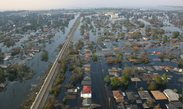
Figure 1: (Hypothetical) Flooding of Wyandotte, MI (www.wunderground.com)
1.1 Background History of Ioskeha
In the spring of 2014, the lives of the 25,000+ citizens of Wyandotte, Michigan changed forever. A historic flooding of the Detroit River led to major devastation in the city. Most of the infrastructure, including the roads, public buildings, and residential households, were wiped out. Instead of moving away from their beloved hometown, the citizens of Wyandotte came together to rebuild and recreate. They started by changing the name of the city to Ioskeha, named after the sun-god of the Iroquois, who originally had a small village on the site. With the sun-god on their side, the citizens began promoting a green culture throughout the city through teaching and volunteering, as well as implementing green engineering in the rebuilding of the infrastructure of the city. While the city is still under construction, the changes that have already been have been favorable amongst the citizens and have set the example for other, potentially green communities to follow.
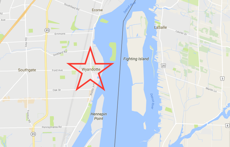
Figure 2: Location of Wyandotte, MI, now Ioskeha. (Google Maps)
1.2 Becoming a Green Community
After hearing about the flooding in Ioskeha, a former resident who moved to Georgia to attend the University of Georgia’s environmental engineering program and went on to start her own environmental engineering consulting firm, moved back home to help the citizens of her hometown start over. With help from the firm, the citizens were able to implement changes to make their city more environmentally friendly. They started with the energy source. Wind turbines were built just outside the city to provide a renewable source of energy to the city. In addition, a biomass plant was also built outside the city to provide an additional source of energy. The biomass plant also provided jobs to the city after the flood. The plant runs off of burning wood. A natural gas electric generating plant located in the next town is used as a backup source of energy when the wind turbines and biomass plant are not enough to provide the residents with adequate energy. However, the natural gas backup source to the city has rarely been in service since the flood because energy efficient buildings and homes were designed for the city. Most homes and public buildings house EnergyStar appliances, which are much more efficient than other appliances. In addition, LED lighting was installed for all public street lights, and citizens were offered discounted LED lighting for their homes if they chose to install them. Biking and public transportation are strongly encouraged throughout the city with biking lanes designed for every major road in the city and electric public buses making stops inside and outside the city. An electric car sharing program was implemented to encourage less driving as well, and electric car charges were installed at all public buildings to encourage residents to purchase electric cars. A green culture was started in the city of Ioskeha as well. In order to promote a "green culture", Ioskeha has encouraged citizen and community involvement. This includes a community garden, where local high school students can volunteer as a class elective, weekly classes about new green engineering and energy technologies, and monthly meetings to discuss changes that can be made to make the community even better.
1.3 Firm Introduction and Goal
The firm hired to help rebuild the city, founded by a former Wyandotte resident and UGA alum, is LSE Engineers, Inc. This firm focuses on green engineering and producing sustainable design projects. LSE Engineers, Inc. focuses on affordable, sustainable, context sensitive designs that are approved and supported by all citizens wherever they are serving. LSE Engineers incorporates a number of principles to help promote green engineering and sustainable development. LSE Engineers work to use nonhazardous materials, as well as materials that can be recycled or reused for another purpose after they are used in the design. These materials must be durable, able to withstand many years to avoid rebuilding/replacing and wasting material. In addition, LSE Engineers makes sure that the materials and components used in the design are easily dismantled and replaced if necessary over the lifetime of the facility. LSE Engineers focuses on producing as little wastes as possible, both during the building process and after the facility/building has been completed. For this water treatment design, the building process will focus on limiting waste from materials and reusing materials when applicable, while the actual design of the facility will reuse and recycle water back into the system. In addition, the building process will focus on using efficient technology and methods to limit energy, material, and space consumption. The final design will be efficient as well to prevent unnecessary wastes. This water treatment facility will run off of renewable power from the wind turbines, with natural gas fired power serving as the backup electricity when the wind power isn’t sufficient. The facility will have a green roof with a small garden, and some of the reclaimed water from the treatment will be used to irrigate the garden and roof. The facility will also have lighting and faucet sensors to prevent energy and water waste. In addition, the facility is designed to follow the natural contour of the land, so that the water will flow on its own instead of requiring multiple on-site pumps.
1.4 Public Meeting Notice
The design for this water treatment facility is being proposed on September 28th at 12:30pm in a town hall type meeting. As citizens of Ioskeha, you are encouraged to attend if possible, and all questions and concerns will be addressed.
1.5 Report Objectives
In addition to the proposal of the project at the meeting on Wednesday, September 28th, this report is designed to outline the new water treatment facility for the city of Ioskeha. This facility is being designed to serve a population of 25,000+ people, which takes into account the possibility of future growth, and it will take in water from the Detroit River. This report will discuss the background of the facility, including addressing some drinking water standards and river protection standards, the proposed facility location, the actual design of the facility, including each step necessary to provide safe and reliable drinking water, and all of the requirements that must be met to ensure safe water quality standards. Once again, this is the proposed solution for the water treatment facility. All concerns for this design will be addressed at the town hall meeting.
2.0 Background
2.1 Surface Water Standards
This drinking water facility will take water from the Detroit River to use as drinking water. The Detroit River is used for transportation and recreation in addition to the small amount that will be taken out for use at the drinking water facility. In 1972, the Clean Water Act was established by the EPA to regulate the quality standards for surface waters, which include the river. Under the Clean Water Act, the state is responsible for establishing these water quality standards. For surface waters in the state of Michigan, the maximum level of benzene in terms of Human Cancer Values (in is 12 for drinking water and 310 for non-drinking water. This level refers to the “the maximum ambient water concentration of a substance at which a lifetime of exposure from either drinking the water, consuming fish from the water, and conducting water-related recreation activities or consuming fish from the water and conducting water-related recreation activities will represent a plausible upper bound risk of contracting cancer of 1 in 100,000” (EPA.gov). Benzene in waterways can often come from factory discharges, as well as gas leakages from storage tanks and landfills. In addition, the dissolved oxygen in rivers in Michigan must meet the minimum level of 5 mg/L of DO, a regulation imposed by the EPA as part of the Clean Water Act.
2.2 Drinking Water Standards
In addition to the Clean Water Act, the Safe Drinking Water Act was established in 1974 to ensure that the public has access to safe drinking water. Under the Safe Drinking Water Act, the EPA sets standards for drinking water quality and makes sure that all states implement these standards. The standards are set as maximum contamination level goals and maximum contamination levels. In Michigan, the Department of Environmental Quality enforces the regulations set by EPA under the Safe Drinking Water Act. There are five different classifications of water supply as listed by the DEQ. They are broken down as follows: Type I community public water supply (municipalities, apartments, etc.), Type II nontransient noncommunity water supply (schools, industries, etc.), Type II transient noncommunity water supply (hotels and restaurants), Type III public water supply (small apartment complexes, condominiums, etc.), and private water supply (households). These public water supplies adhere to the standards and treatment techniques set for all public water supplies. For public drinking water supplies in Michigan, the maximum contamination level of benzene is .005 mg/L, while the maximum contamination level goals is 0 mg/L. Anything over .005 mg/L could cause adverse health effects. The arsenic MCL is .01 mg/L, while the maximum contamination level goal is 0 mg/L as well. Like benzene, any supply that reaches levels above this maximum contamination level of arsenic could lead to adverse health effects as well.
2.3 Drinking Water Treatment Plant Location and Max Demand
This drinking water plant will be located far enough downstream from all industries and factories to ensure that the drinking water standards are met. For example, CBOD, or carbonaceous biological oxygen demand, is a very important water quality standard. LSE Engineering Firm was able to calculate the distance downstream the drinking plant needed to be located from a factory by using the maximum 5 day CBOD allowed, along with some information about the discharge from the industry and the size of the river. For example, if a river has a cross sectional area of 48, a calculated velocity of 9.003 km/day, a max 5 day CBOD downstream of 50 mg/L or less, and an ultimate CBOD of 194.7 mg/L after the waste has mixed with the stream water, then the drinking water facility would need to be placed at least 38.4 kM downstream from the waste disposal in order to meet the CBOD of 50 mg/L or less. These calculations can be found in the appendix. In addition, based on the population trend found in Ioskeha, the firm was able to predict for future population growth and create minimum, maximum, and average water demand per day for the city. Since the population trend was decreasing before the disaster, the firm decided to use the current population as the max population now and the max population in 25 years. The firm does not believe the population will reach that number, but used it as a factor of safety. Based on the current population of 25,592 people, and the average, maximum, and minimum gallons per day per persons set demands, the firm determined that the average gallons per day needed at this facility would be 2,994,264 gallons to supply water to the entire city. This flow rate was used for a large majority of the calculations that were made to design this drinking water facility. The maximum demand flow rate, calculated to be 4,478,600 gallons per day, was also used for some of the calculations when a larger factor of safety was necessary. The image below highlights the proposed location of the drinking water facility on the Detroit River.

Figure 3: Image of proposed location for drinking water facility. (Google Maps)
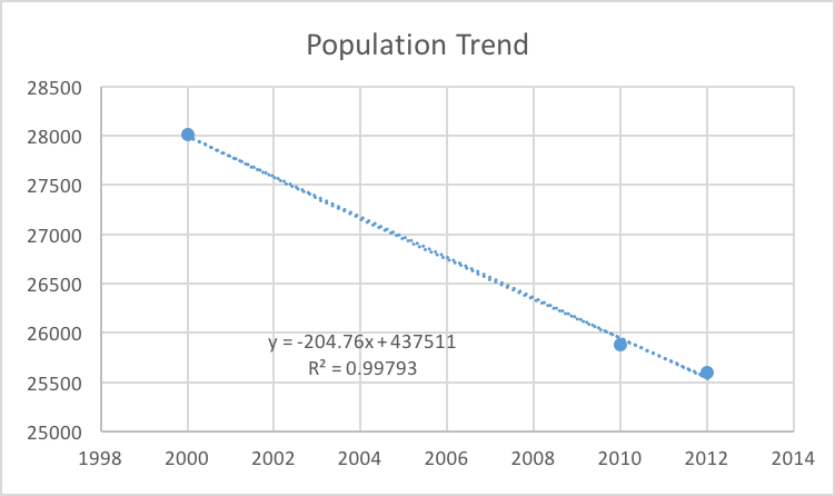
Figure 4: Predicted population trend; since it is decreasing, LSE decided to use the current population as the max population.
3.0 Water Treatment Facility Design
3.1 Overall Design Goal and Purpose
The overall purpose of this facility design is to treat water from the Detroit River in order to provide both potable and palatable water to the residents of Ioskeha. This means that the water is free any harmful compounds or organisms and is healthy to drink, while also being aesthetically pleasing to the consumers. In addition, this drinking water plant is also going to recycle and reuse some of the water in order to use all the resources available in the most efficient manner. The reclaimed water from the facility will be used to irrigate the green roof on the facility. Below is a schematic of the steps that will be taken to treat the water from the Detroit River and distribute it to the citizens of Ioskeha. The treatment process will be described step-by-step in this report.
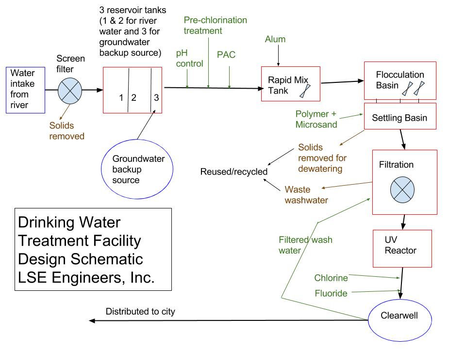
Figure 5: Proposed design schematic for the drinking water treatment facility
3.2 From the River to the Reservoirs
The first step in the drinking water facility is to divert the water from the river. Since the facility is located on the river, the water does not have to be transported very far. The water flows into pipes from the river and passes through screens that filter out solid particles from the water. The water is stored in reservoir tanks located just outside the facility. These tanks hold enough water to supply the city for 30 days at all times in case of a disaster. There are two reservoir tanks, each holding 44,913,960 gallons of water. They are closed in, covered reservoirs due to the harsh winter weather that hits Michigan each year.
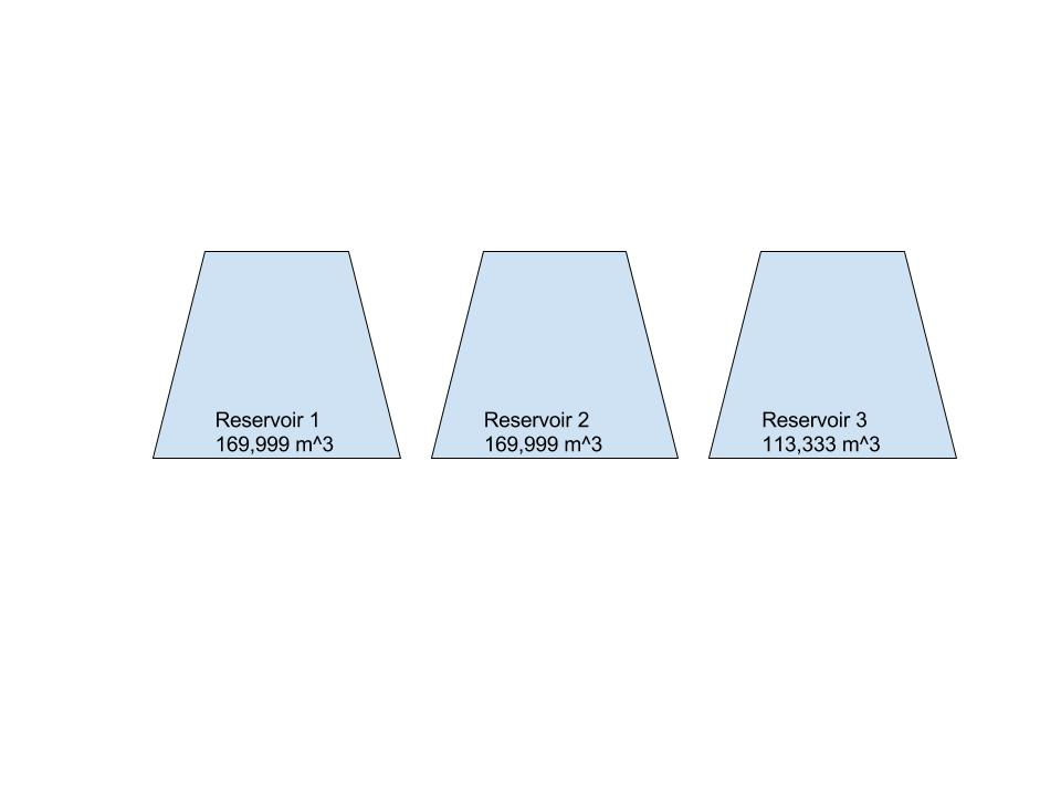
Figure 6: Drawing of the three reservoirs on site (two for river water and one for groundwater).
3.3 Chemical Add-Ins Before Rapid Mix Tank
From the tanks, the water flows through pipes following the natural slope of the land to the facility’s rapid mix tank. While the water is flowing through the pipes, it is treated for pH control and disinfected. To control pH, sodium hydroxide is added to the water to keep the pH level as close to 7 as possible. A pre-chlorination treatment of chlorine gas is added to disinfect the water. In addition, powdered activated carbon is added to help the palatable qualities of the water, such as taste and odor. A coagulant is then added to the flowing water as it enters the rapid mix tank. Coagulants are chemicals that are added to water to destabilize particles and encourage coagulation, or clotting. As a part of this process, the turbidity of the water is also reduced. At this facility, the coagulant used is alum. Based off of Jar Testing of the water source, LSE Engineering determined that the optimum alum dosage is 3 mg/L for this water. Using this dosage, 1.515 mg/L of alkalinity as are consumed. This was proven to be low enough for the alkalinity in the raw water to buffer against after the alum addition. Using the average gallons per day flow rate of 2,994,264 gpd (11,333,289 L) and the alum dosage of 3 mg/L, the facility will require 12409.95 kg of alum each year to sufficiently coagulate the water.
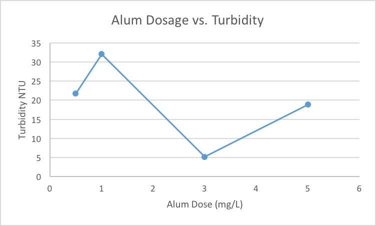
Figure 7: Graph showing the results from the Jar Testing to determine the optimum alum dosage.
3.4 Groundwater as Backup Source
Groundwater serves as the backup source in case of emergencies. In order to use the groundwater as a drinking source, it must be treated for hardness. Hardness is water is generally caused by calcium and magnesium ions. Through a few chemical processes and additions, hardness can be removed from water so that it becomes a safe drinking source. Based on the current chemical constituents of the backup groundwater source, LSE engineers were able to determine the amount of lime and soda-ash that needs to be added to the water to reduce water hardness. This groundwater source must meet the same gallons per day flow rate as the river source in order to provide water to all the residents in the city of Ioskeha, which is equal to 2,994,264 gallons per day. The results of the calculations performed by LSE engineers were as follows: 3948 kg of bulk lime per day will be needed, along with 2543 kg of bulk soda-ash per day, to reduce water hardness. This results in 1,441,020 kg of lime and 928,195 kg of soda-ash needed each year at the water treatment plant. However, since this groundwater source is meant solely as backup in case of emergency, the firm has proposed to keep enough lime and soda-ash on site to last for 30 days. This is equivalent to 118,440 kg of lime and 76,290 kg of soda-ash. There is currently enough groundwater already pumped into an additional reservoir on site to last for 10 days at the average flow rate. Therefore, the city of Ioskeha can last for up to 40 days on the current water stored if needed.
3.5 Rapid Mix Tank
After the water from the river is passed through screens, treated for pH control, disinfected, and alum is added, it is pumped up to a rapid mix tank from the pipes. The rapid mix tank blends the chemicals that were first added to the water with the water to form a mixture. The rapid mix tank is designed to be a conventional stirred tank, and it will have a detention time value of 60 seconds using mechanical mixing. The size of the rapid mix tank was determined based off of the maximum gallons per day flow rate determined previously. Therefore, based off of a flow rate of 16,951,501 liters per day, the tank was sized to be 12 .
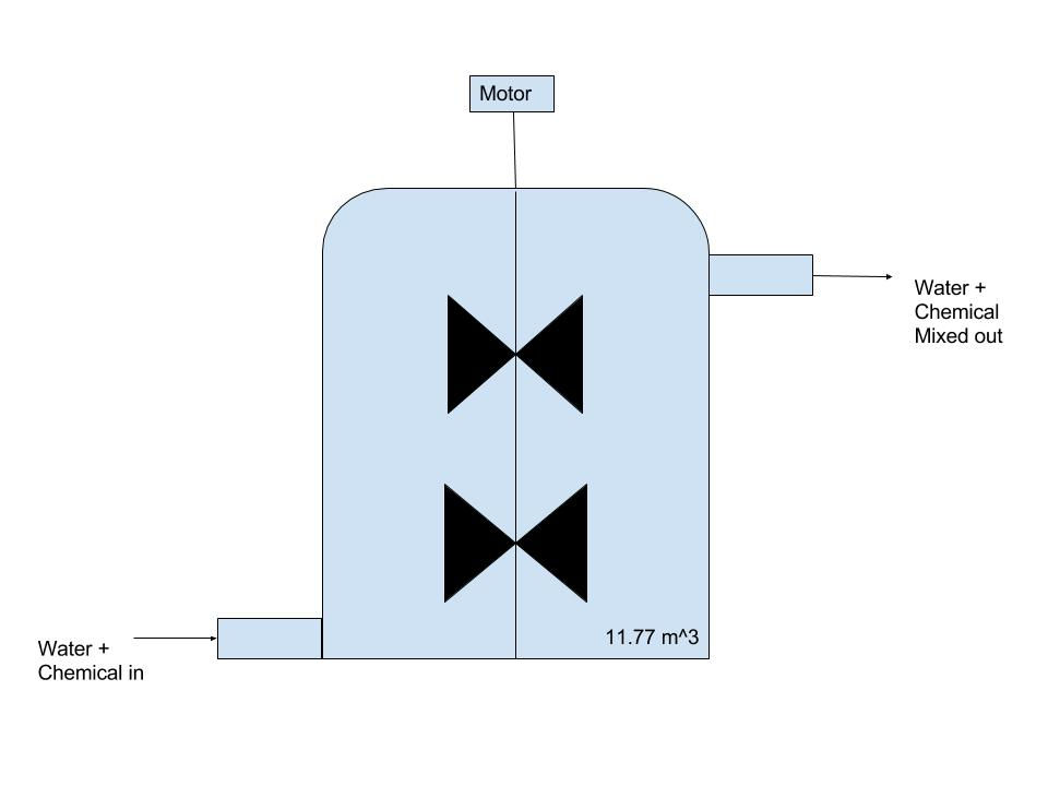
Figure 8: Drawing of the design of the rapid mix tank
3.6 Flocculation Basins
The water then flows out of the rapid mix tank into pipes, which flow downhill to the flocculation basins. The flocculation system at this drinking water treatment facility is a horizontal-shaft paddle wheel flocculation system. These paddles in the basins turn very slowly (less than 1 revolution per minute) and the basins have a detention time of approximately 20 minutes. Therefore, the water in the basins is also moving very slowly. This allows the particles and sediments in the water to clump together to form sticky particles called floc and eventually filtrate out easily.
3.7 Sedimentation Basins
The paddles push the water towards the next section of the water treatment plant. In this section are sedimentation basins. The water flows under the barrier from the flocculation basin to the bottom of the sedimentation basin. In this basin, a polymer and microsand are added to the water. The polymer attaches to the sand and makes it sticky, which allows the sand to attach to the floc and weigh it down. The floc and sediments that were clumped together in the flocculation basins now settle to the bottom of the sedimentation basins due to the extra weight from the sand. It takes around 1-2 hours for sediments from the water to completely settle at the bottom of the basin. This sediment at the bottom of the basin is removed from the basins and taken to other parts of the facility for further processing.
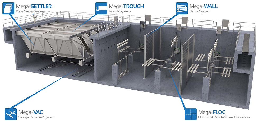
Figure 9: The flocculation and sedimentation basin proposed design. (www.jmsequipment.com)
3.8 Filtration
The next step in the process is filtration. The water flows from pipes connecting to the basin into another basin that has filters on the bottom. The water flows through these filters, which are made from anthracite, a type of hard coal, and sand. This is referred to as rapid sand filtration. There will be two rapid sand filters at this drinking water facility. Once a day, the filters must be washed to avoid clogging. This takes fifteen minutes, during which only one filter will be operational. The water will be tested after this step for turbidity to make sure that the drinking water standards are being met.
3.9 UV Disinfection
From there, the water flows to a UV light reactor that disinfects the water by sterilizing bacteria. In addition, chlorine is added to the water for further disinfection. The temperature of the water is kept at 12℃ throughout the process, so the amount of chlorine needed at this stage in the treatment process was determined from standards for water at that temperature. The engineering firm calculated the amount of chlorine needed to be 2330.5 g chlorine per year. The chlorine will be kept in secure tanks on site and monitored daily for any sort of leaks or problems. In addition, fluoride is also added at this stage in the process. The fluoride standard for this facility is set at 4 mg/L, which means that approximately 16,547 kg of fluoride is needed per year at the facility (if there is already no fluoride present in the water).
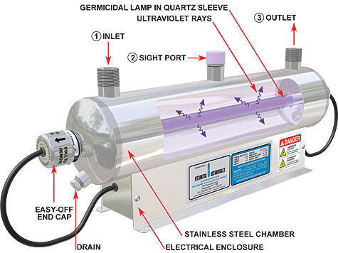
Figure 10: UV Reactor for sterilization of bacteria (www.freshwatersystems.com)
3.10 Clearwell storage
After disinfection, the water flows to a large storage tank called a clearwell. The clearwell is designed to hold the average daily demand for the city, or 11,333,289 L. The clearwell is therefore sized at 11,333 . This is so that the water does not deteriorate before it is able to be distributed. In the clearwell, the water is stored until it is distributed through underground pipelines to all residential homes, businesses, schools, hospitals, etc. throughout the city. During this treatment process, some water and solids are removed from the system. Most of the water and solids are recaptured and reused. The solids are dewatered, and that water, along with any other wastewater, is piped back to the beginning of the process for reuse. In addition, some of the reclaimed water is used for the irrigation of the green roof on the top of the building. Every day, the water is monitored and tested to ensure that the plant is meeting water quality standards.
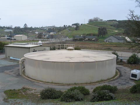
Figure 11: Clearwell proposed design (www.ccwd.org)
4.0 Summary
4.1 Design Summary
This report lays out the design plan for the drinking water treatment plant for the city of Ioskeha and its 25,000+ residents. The design incorporates green engineering by reusing water, minimizing energy use and wastes, installing light and faucet sensors, running off of renewable power, and establishing a green roof. It also meets the standards for safe drinking water quality set by the EPA, and is monitored daily to ensure that the standards are continuously met throughout the treatment process.
4.2 Public Meeting Notice
This is a design proposal, and the firm, LSE Engineering, Inc., will host a town hall meeting on Wednesday, September 28th at 12:30pm to discuss the proposal and address any questions or concerns
References
Auer, Martin T., James Mihelcic R., and Julie Zimmerman Beth. Environmental Engineering: Fundamentals, Sustainability, Design. Hoboken, NJ: John Wiley & Sons/Wiley, 2010. Print.
Brian Christianson and Reno Fiorante. "Saving Water, Seeing Green: Water Treatment Plant Strives for Sustainability." - WaterWorld. PennWell Corporation, n.d. Web. 27 Sept. 2016.
"DEQ." - Department of Environmental Quality. State of Michigan, n.d. Web. 28 Sept. 2016.
"Public Health Regulations." Handbook of Drinking Water Quality (n.d.): 401-17. Web.
Quality, Michigan Department Of Environmental. Administrative Rules, Part 4, Water Quality Standards (n.d.): n. pag. Web.
"US Environmental Protection Agency." EPA. Environmental Protection Agency, n.d. Web. 28 Sept. 2016.
http://w3.lara.state.mi.us/orr/Files/AdminCode/1346_2014-023EQ_AdminCode.pdf
Image References:
Figure 1: wunderground.com
Figure 2 & 3: Google Maps
Figure 9: jmsequipment.com
Figure 10: freshwatersystems.com
Figure 11: ccwd.org


Comments