

Design Project 2 - Wastewater Treatment Facility
- Nov 2, 2016
- 16 min read
1.0 Introduction

Figure 1: (Hypothetical) Flooding of Wyandotte, MI (www.wunderground.com)
1.1 Background History of Ioskeha
In the spring of 2014, the lives of the 25,000+ citizens of Wyandotte, Michigan changed forever. A historic flooding of the Detroit River led to major devastation in the city. Most of the infrastructure, including the roads, public buildings, and residential households, were wiped out. Instead of moving away from their beloved hometown, the citizens of Wyandotte came together to rebuild and recreate. They started by changing the name of the city to Ioskeha, named after the sun-god of the Iroquois, who originally had a small village on the site. With the sun-god on their side, the citizens began promoting a green culture throughout the city through teaching and volunteering, as well as implementing green engineering in the rebuilding of the infrastructure of the city. While the city is still under construction, the changes that have already been have been favorable amongst the citizens and have set the example for other, potentially green communities to follow.
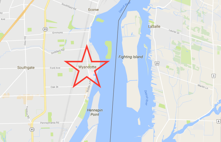
Figure 2: Location of Wyandotte, MI, now Ioskeha. (Google Maps)
1.2 Becoming a Green Community
After hearing about the flooding in Ioskeha, a former resident who moved to Georgia to attend the University of Georgia’s environmental engineering program and went on to start her own environmental engineering consulting firm, moved back home to help the citizens of her hometown start over. With help from the firm, the citizens were able to implement changes to make their city more environmentally friendly. They started with the energy source. Wind turbines were built just outside the city to provide a renewable source of energy to the city. In addition, a biomass plant was also built outside the city to provide an additional source of energy. The biomass plant also provided jobs to the city after the flood. The plant runs off of burning wood. A natural gas electric generating plant located in the next town is used as a backup source of energy when the wind turbines and biomass plant are not enough to provide the residents with adequate energy. However, the natural gas backup source to the city has rarely been in service since the flood because energy efficient buildings and homes were designed for the city. Most homes and public buildings house EnergyStar appliances, which are much more efficient than other appliances. In addition, LED lighting was installed for all public street lights, and citizens were offered discounted LED lighting for their homes if they chose to install them. Biking and public transportation are strongly encouraged throughout the city with biking lanes designed for every major road in the city and electric public buses making stops inside and outside the city. An electric car sharing program was implemented to encourage less driving as well, and electric car charges were installed at all public buildings to encourage residents to purchase electric cars. A green culture was started in the city of Ioskeha as well. In order to promote a "green culture", Ioskeha has encouraged citizen and community involvement. This includes a community garden, where local high school students can volunteer as a class elective, weekly classes about new green engineering and energy technologies, and monthly meetings to discuss changes that can be made to make the community even better.
1.3 Firm Introduction and Goal
The firm hired to help rebuild the city, founded by a former Wyandotte resident and UGA alum, is LSE Engineers, Inc. This firm focuses on green engineering and producing sustainable design projects. LSE Engineers, Inc. focuses on affordable, sustainable, context sensitive designs that are approved and supported by all citizens wherever they are serving. LSE Engineers incorporates a number of principles to help promote green engineering and sustainable development. LSE Engineers work to use nonhazardous materials, as well as materials that can be recycled or reused for another purpose after they are used in the design. These materials must be durable, able to withstand many years to avoid rebuilding/replacing and wasting material. In addition, LSE Engineers makes sure that the materials and components used in the design are easily dismantled and replaced if necessary over the lifetime of the facility. LSE Engineers focuses on producing as little wastes as possible, both during the building process and after the facility/building has been completed. For this water reclamation facility design, the building process will focus on limiting waste from materials and reusing materials when applicable, while the actual design of the facility will reuse and recycle as much water and microorganisms as possible back into the system. In addition, the building process will focus on using efficient technology and methods to limit energy, material, and space consumption. The final design will be efficient as well to prevent unnecessary wastes. This water reclamation facility will run off of renewable power from the wind turbines, with natural gas fired power serving as the backup electricity when the wind power isn’t sufficient. Some of the reclaimed water from this facility will be used to irrigate the land surrounding the facility. The facility will also have lighting and faucet sensors to prevent energy and water waste. In addition, the facility is designed to follow the natural contour of the land, so that the water will flow on its own instead of requiring multiple on-site pumps.
1.4 Public Meeting Notice
The design for this water treatment facility is being proposed on November 2nd at 12:30pm in a town hall type meeting. As citizens of Ioskeha, you are encouraged to attend if possible, and all questions and concerns will be addressed.
1.5 Report Objectives
In addition to the proposal of the project at the meeting on Wednesday, November 2nd, this report is designed to outline the new water reclamation facility for the city of Ioskeha. This facility is being designed to treat the wastewater from a population of 25,000+ people, which takes into account the possibility of future growth, and it will release the treated water back into the Detroit River. This report will discuss the background of the facility, including addressing some wastewater standards and river protection standards, the proposed facility location, the actual design of the facility, including each step necessary to safely discharge reclaimed water back into the river, and all of the requirements necessary to ensure that safe wastewater quality standards are met. Once again, this is the proposed solution for the water reclamation facility. All concerns for this design will be addressed at the town hall meeting.
2.0 Background
2.1 Influent Concentrations
The purpose of this municipal wastewater treatment facility is to prevent pollution of the Detroit River when the wastewater is put back into the river, and to prevent any problems associated with human health for the citizens of Ioskeha. Untreated wastewater contains a number of pollutants, including depleted dissolved oxygen content, total suspended solids, nitrogen and phosphorus, which lead to eutrophication, toxic chemicals, soaps and detergents, and different pathogens like coliform bacteria. If wastewater is not treated before it is placed back in the river, it can cause major human health problems, as well as problems for the fish and wildlife in the river. Although the amount of pollutants per unit of wastewater may seem small, these pollutants are still very dangerous in those small amounts. Incoming wastewater to the facility will generally be gray in color, around 15°C, and will appear very turbid. The average biochemical oxygen demand (BOD) concentration for this influent water to this facility is around 200 mg/L. Comparatively, the BOD concentration of a river is around 2 mg/L, so one purpose of this facility is to reduce that concentration. The influent suspended solids concentration will be around 240 mg/L, with total solids reaching around 800 mg/L. These solids cause the water to be turbid, and they can contain organic matter, pollutants, and pathogens. Since these solids can lead to many human health and wildlife problems, they must be removed before being discharged into the river. The influent pathogen concentration is approximately 3 million coliforms per 100 mL, which is a very dangerous amount if not treated. Nitrogen and phosphorus are also present in influent water. The total nitrogen average concentration is around 35 mg/L, with 15 mg/L of that being inorganic nitrogen. The total average phosphorus concentration for influent wastewater is 10 mg/L. These nutrients can cause eutrophication, which is very dangerous in waterways and can lead to the death of the water bodies. Toxic chemicals, such as heavy metals and pesticides, will vary in their concentration in the influent wastewater. However, they will still need to be treated to avoid health and waterway risks. In Section 2.3, the discharging standards for the above pollutants will be discussed.
2.2 Flow Rates
This water reclamation facility is designed to accommodate the wastewater for Ioskeha’s current population. Like the drinking water facility, this population does account for population growth in the future because Ioskeha’s population is actually decreasing over time. The current population is 25,592 people. The average wastewater generated per person per day for the city of Ioskeha was determined to be 87 gallons. Therefore, the facility had to be designed to accommodate 2,226,504 gallons of wastewater each day. All of the designs in this report adhere to that amount. In addition, the peak hourly flow rate was found to be 1.57 , which was used for some of the design calculations when necessary, and the average hourly flow rate was found to be .55, which was used for the majority of the design calculations.
2.3 Water Discharge Standards
The Clean Water Act of 1972 was the first national act that aimed to protect water from pollution. The goal of the act was to reach a level of water quality in all of the nation’s waters that protected the fish and wildlife in the waters, allowed for safe recreational use of the waters, and prevented the dumping of untreated wastewater into the waters (EPA.gov). In order to prevent the discharge of wastewater into national water bodies, the National Pollutant Discharge Elimination System (NPDES) was established to enforce regulations of wastewater at the state level. This design project will adhere to all EPA and NPDES standards. Some concentration standards set by the EPA and NPDES included BOD, suspended solids, pathogens, nitrogen and phosphorus, toxic chemicals, and pH. The BOD standards are set at 30 mg/L for 30-day BOD concentration and 45 mg/L for 7-day BOD concentration. For this design, the BOD standard for the design calculations was set at 30 mg/L as the allowable BOD concentration. The total suspended solids (TSS) concentration standards are also set at 30 mg/L for the 30-day allowable TSS concentration and 45 mg/L for the 7-day allowable TSS concentration. For this project, LSE Engineering, Inc. will be using a standard of 36 mg/L for the 30-day allowable standard for TSS concentration in the discharged wastewater. This is the standard used by most facilities that discharge into the Detroit River, which is where this facility will discharge the water. The standards for pathogens, like fecal coliform, depend on the NPDES set standards for each state. For the state of Michigan, the NPDES has set the standard for fecal coliform at 200 counts/mL (or less) for the 30-day allowable concentration, and 400 counts/mL for the 7-day allowable concentration for discharged water. Nutrients such as phosphorus and nitrogen that may be discharged into waterways are also monitored by the NPDES. Phosphorus concentration has been set at 1 mg/L as the maximum monthly average. The nitrogen concentration is “limited to the extent necessary to prevent stimulation of growths of aquatic rooted, attached, suspended, and floating plants, fungi or bacteria which are or may become injurious to the designated uses of the surface waters of the state” (DEQ), which could vary from facility to facility. Toxic chemicals will also be monitored in the water before it is discharged, but there are a number of different standards depending on which type of chemical may be found in the water. In general, most toxic chemicals are removed during the wastewater treatment processes, and therefore they never make it to the discharge point and do not harm humans or wildlife. The pH of the water will also be tested before it is discharged. The pH must be between 6.5 and 9.0 in accordance with the Michigan Water Quality Standards.
2.4 Location of Facility
The facility will be located downstream from both the town and the location where the drinking water is taken in from the river. This is to prevent the wastewater from being used as drinking water for the town of Ioskeha. It is also far enough upstream from any other towns to prevent contamination in the other towns’ drinking water sources. However, the discharged water will adhere to all standards set by the EPA and NPDES, so if it is used downstream as a drinking water source, it will be safe to drink once treated at the drinking water facility. The image below highlights the proposed location of the water reclamation facility on the Detroit River.

Figure 3: Image of proposed location for the water reclamation facility. (Google Maps)
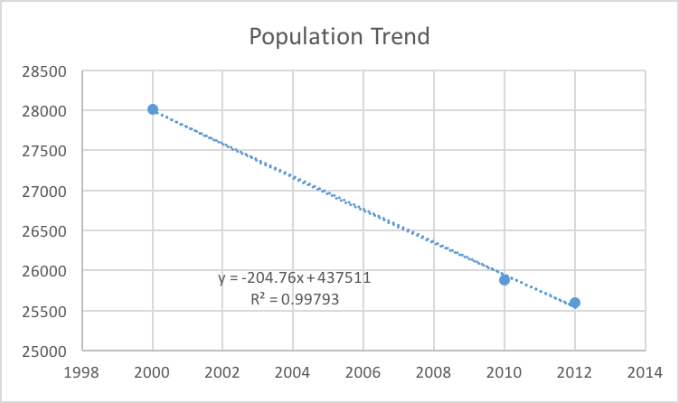
Figure 4: Predicted population trend; since it is decreasing, LSE decided to use the current population as the max population.
3.0 Water Reclamation Facility Design
3.1 Overall Design Goal and Purpose
The overall purpose of this facility design is to treat the residential wastewater and storm water from the citizens of Ioskeha in order to prevent the pollution of the Detroit River and to prevent human health issues when the wastewater is discharged. This facility will follow the contour of the land to prevent unnecessary pumping. Some of the reclaimed water from the facility will be rerouted and used to irrigate the land surrounding the facility. In addition, the water will be conserved in every step of the design in order to prevent additional water from being wasted in the reclamation process.

Figure 5: Proposed design schematic for the reclaimed water treatment facility
3.2 From the Sewer to the Headworks
The first steps in the wastewater treatment facility fall under preliminary treatment of the wastewater. The wastewater from residential households flows through pipes into the sewers, where storm water also collects. All of the wastewater then flows from the sewers to the wastewater treatment plant. At the facility, the wastewater flows through huge bar screens that collect the large particles that may have gotten into the sewer. The screens are continuously cleaned with automatic rakes, and the large particles are sent to the landfill. The screens are located on site 10m above sea level, with the rest of the facility below that height so that the water is able to flow naturally downhill.

Figure 6: Bar screens used to remove large particles (www.industrial-wastewatertreatment.com)
3.3 Aerated Grit Chamber
After the wastewater is removed of any large particles that may clog the rest of the system, the water flows downhill to the aerated grit chamber. The water flows approximately 1m downhill in height, reaching the grit chambers that are sitting at 9m above sea level. The aerated grit chambers are used in the system to remove grit from the wastewater before it flows through the pipes into the primary settling tank. If it is not removed, the grit may abrade the pipes and equipment in the system. The grit that is removed includes sand, gravel, and some organic matter. For this facility design, LSE Engineering, Inc. decided to add grit-washing equipment. This equipment removes the organic matter from the chamber so that it may be reused and recycled. For this facility, two aerated grit chambers were designed. A detention time of 3 minutes was used for the design. The volume of each of the chambers were determined based off of the peak hourly flow rate and the detention time. The total volume was divided into the two tanks evenly. This volume, as well as Table 9.4 from Environmental Engineering, was used to determine the width, depth, and height of the chambers. The chart below shows the dimensions of the chambers.

Figure 7: Chart showing the dimensions of each aerated grit chamber
The average hydraulic detention time in each chamber was determined using the rounded volume (based off of the determine width, length, and height) and the average hourly flow rate. This average hydraulic detention time was found to be 8.73 minutes. In addition, the total air requirement for both chambers was found to be 4.8 of air. Finally, the total amount of grit that would be removed in volume per day was determined. This value was determined based off of the peak hourly flow rate. The total grit volume removed by the two tanks each day was found to be 2.713

Figure 8: Drawing of aerated grit chambers similar to ones used in this facility proposal design (http://web.deu.edu.)
3.4 Primary Settling Tank
The next step used to treat the wastewater is primary settling. Primary settling is a part of the primary treatment of the water with the goal is to remove solids and particles through settling. For this design, two circular primary settling tanks are designed to allow the wastewater to go through primary treatment. They are located at 7m above sea level, 2m below the previous step. In these tanks, the solids will settle at the bottom of the tank and will be removed. They will then be sent to landfills or composting sites. Primary treatment of the water removes a majority of the total suspended solids in the wastewater, and it removes a smaller amount of BOD and phosphorus from the water. The area of each tank was determined using the average flow rate and the surface overflow rate. The areas were rounded up to make the building process of the tanks easier. The total area for each clarifier was calculated to be 530.9 and the total volume for each clarifier was determined to be 1592.8 based off of a depth of 3m. In addition, both the average and peak flow rates were used to determine the hydraulic detention times and the observed overflow rates for each tank. The chart below summarizes the results in a simplistic manner.

Figure 9: Chart comparing the results for the primary clarifiers using the average flow rate and peak flow rate

Figure 10: Simplistic drawing of a primary settling tank similar to those designed for this facility.
3.5 Aeration Basin and Secondary Clarifiers
The next stage in wastewater treatment is secondary treatment. This is accomplished through an aeration basin. Water flows from the primary settling tank to the aeration basin, which sits at 5m above sea level. In this basin, the water is mixed with different microorganisms. These organisms include bacteria, fungi, protozoa, and rotifers. This mixture is known as mixed liquor. Oxygen is also added to the mixture to degrade the presence of BOD. These added microorganisms stick the pathogens found in the wastewater and help to remove their presence. The majority of the harmful pathogens in the wastewater are consumed by the microorganisms in this stage of the treatment process. The microorganisms and water mixture then flow to the secondary clarifier in order to settle out. This clarifier is located at 3m above sea level to allow for the natural flow of water. In the secondary clarifier, the microorganisms settle to the bottom of the tank. Some of the microorganisms are starved and can be used again in the treatment process. This sludge is called return activated sludge, and it is pumped back to the beginning of the aeration basin process so that the microorganisms can be used again. The rest of the microorganisms are deemed waste activated sludge. At this point, they are removed from the clarifier and dewatered. The solids are sent to compost sites.
Based off of the lab results collected for the design of this facility, the incoming value for all of the wastewater coming to the plant was determined to be 301.2525 mg/L. The lab result for the COD, or chemical oxygen demand, concentration used in this calculation was 859 mg/L. This result was slightly higher than the normal range of 300-700 mg/L for plant influent, but it was okay to use for the general design of this facility. Using Equation 9.11 from Environmental Engineering, the volume of the aeration basin design was determined. The volume of the basin was determined to be The aeration period for the wastewater was calculated to be 2.63 hours. Based on TSS concentration results taken from the wastewater, as well as from different stages of the treatment process, the amount (in kg/day) of primary and secondary solids generated during the treatment process was determined. Approximately 1096 kg/day of primary solids will be generated, while 609.7 kg/day of secondary solids will be generated at the plant. (Equation 9.1 from Environmental Engineering). The food to microorganism ratio was also determined using Equation 9.16 from Environmental Engineering. This ratio is the feeding rate of the microorganisms. If the F/M ratio is low, the feeding rate will be low, which creates hungrier microorganisms. Hungry microorganisms lead to a more efficient removal processes. In addition, if the solids retention time (SRT) is really low, the F/M ratio will in turn be high, which is the case in this facility. This leads to shorter hydraulic residence times and smaller aeration tanks, which are the design parameters that LSE Engineering, Inc. focused on. For this facility, the F/M ratio was calculated to be .583 where MLSS stands for mixed liquor suspended solids, which is just the measurement of TSS taken in the aeration basin. As mentioned earlier, this high F/M ratio leads to shorter hydraulic residence times and a smaller volume for the aeration basin. It also means that less power is necessary to be supplied to the aeration basin, which saves on energy costs and consumption, that the microorganisms are saturated, so they will not work as efficiently, that the sludge age will be low since it will not sit in the basin for long periods of time, and that the sludge wastage rate and MLSS may have increased at some point in the process.

Figure 11: Image of an aeration basin similar to the proposed design for this facility (alliancepower.com)

Figure 12: Image of a two secondary clarifiers in Lincoln, NE; similar to the design for the proposed facility outlined in this report (Lincoln.ne.gov)
3.6 UV Disinfection
The last stage before discharging is UV disinfection. The UV disinfection system is located at 1m above sea level, and it is located right next to the point of discharge. The UV system disinfects all leftover bacteria in the water that was not cleared out during the previous stages by sterilizing the bacteria to prevent them from reproducing. Below is an image of an example of a UV disinfection system. This system is located at a wastewater treatment plant in Parker, Colorado.

Figure 13: Image of a UV disinfection system from a facility in Parker, Colorado (http://repository.uwyo.edu)
3.7 Discharging to River
Finally, after all of these steps, the water can be discharged into the river. After passing through the treatment facility, the water is now considered safe enough, by both Michigan and EPA standards, to be discharged into the Detroit River without any harmful side effects. Before discharge, the water is tested and monitored for all water quality standards, including TSS, pH, fecal coliform, dissolved oxygen content, nitrogen and phosphorus levels, and toxic chemical levels. There are backup processes in place if contamination ever occurs. The facility is also monitored 24/7 and the water quality standards are tested at each stage in the process multiple times a day.
4.0 Summary
4.1 Design Summary
This report lays out the design plan for the wastewater treatment plant for the city of Ioskeha and its 25,000+ residents. The design incorporates green engineering by reclaiming water, minimizing energy use and wastes, installing light and faucet sensors, running off of renewable power, and limiting pumping stations by following the slope of the land. It also meets the standards for safe water quality discharge levels set by the EPA and NPDES, and is monitored daily to ensure that the standards are continuously met throughout the treatment process.
4.2 Public Meeting Notice
This is a design proposal, and the firm, LSE Engineering, Inc., will host a town hall meeting on Wednesday, November 2nd at 12:30pm to discuss the proposal and address any questions or concerns.
References
Auer, Martin T., James Mihelcic R., and Julie Zimmerman Beth. Environmental Engineering: Fundamentals, Sustainability, Design. Hoboken, NJ: John Wiley & Sons/Wiley, 2010. Print.
"DEQ." - Department of Environmental Quality. State of Michigan, n.d. Web. 28 Sept. 2016.
"Public Health Regulations." Handbook of Drinking Water Quality (n.d.): 401-17. Web.
Quality, Michigan Department Of Environmental. Administrative Rules, Part 4, Water Quality Standards (n.d.): n. pag. Web.
"US Environmental Protection Agency." EPA. Environmental Protection Agency, n.d. Web. 28 Sept. 2016.
http://w3.lara.state.mi.us/orr/Files/AdminCode/1346_2014-023EQ_AdminCode.pdf
Power point slides from class – Wastewater Treatment 1 and Wastewater 2
Image References:
Figure 1: wunderground.com
Figure 2 & 3: Google Maps
Figure 6: http://www.industrial-wastewatertreatment.com/sale-4410160-municipal-sewage-and-wastewater-bar-screen-mechanically-cleaned-bar-screen.html
Figure 8: http://web.deu.edu.tr/atiksu/ana52/ani4053.html
Figure 10: http://web.eng.fiu.edu/mathmatters/m2ed/wastewatertreatment/lesson1.htm
Figure 11: http://www.alliancepower.com/aeration.html
Figure 12: https://www.lincoln.ne.gov/city/pworks/wastewater/treatment.htm
Figure 13: http://repository.uwyo.edu/cgi/viewcontent.cgi?article=1011&context=honors_theses_15-16


Comments